Applications with exacting requirements in terms of light wavelength or other performance can also be readily addressed, provided that some specific characteristics of LED operation are recognised by the designer.
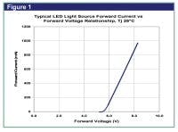
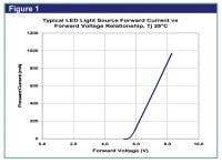
A typical LED forward voltage vs. forward current profile is given in Figure 1. It can be seen that, for a given temperature, a small change in forward voltage produces a disproportionately large change in forward current. In addition, the forward voltage required to achieve a desired light output can vary with LED die size, LED die material, LED die lot variations, and temperature.
By driving LED light sources with a regulated constant-current power supply the light output variation and lifetime issues resulting from voltage variation and voltage changes can be eliminated. Therefore, constant current drivers are generally recommended for powering LED light sources.
For some applications, current-limiting devices such as resistors can be an inexpensive alternative to constant-current drivers for restricting current flow. However, there are many trade-offs. First, resistors generate heat and, therefore, waste power. The heat generated by resistors needs to be dissipated.
In addition, voltage changes from supply voltage variations will translate into changes in light output, and with resistors alone there is no protection for the LEDs to prevent damage from high voltage. A few applications, such as portable lighting, may tolerate these trade-offs but, for most applications resistors are not recommended.
Temperature effects
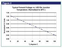
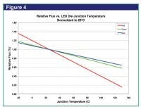
Performance characteristics of LED light sources are specified for a rated current and for an LED die junction temperature of 25°C. Since most LEDs operate well above 25°C, these values should be considered for reference only and the light output should be based on the anticipated operating temperatures.
The light output from an LED light source decreases with increasing LED die junction temperature. Higher LED die junction temperatures, resulting from increased power dissipation or changes in ambient temperature, can have a significant effect on light output.
Red and amber die manufactured from the AlGaInP (aluminium indium gallium phosphorus) material system are more sensitive to temperature effects than blue and green InGaN (indium gallium nitride)-based devices.
In addition to affecting light output, temperature also has an effect on the dominant and peak wavelength. LED die wavelength characteristics are commonly reported at 25°C junction temperatures. With increasing LED die junction temperatures resulting from higher drive currents or ambient conditions, wavelengths typically increase in from 0.03 to 0.13 nm/°C, depending on die type.
Temperature variation can also cause slight shifts in colour temperature for LED white light sources. Applications requiring specific wavelengths or colour temperature should take this effect into account when designing drive conditions and heat sinking.
Electrical design
Driving single LED light sources in non-dimming applications is relatively simple. A constant-current driver is chosen to deliver the desired current, with enough forward voltage output to accommodate the maximum input voltage of the LED source. LED light sources are not designed to be driven with a reverse voltage.
Driving multiple LED light sources with one driver is generally done with the LEDs arranged in series strings to avoid uneven light levels resulting from voltage variations. When selecting a series string driver, the output voltage should be high enough to accommodate the sum of the maximum input voltages of LED light sources.
Dimming and PWM
Dimming LEDs is most commonly done either by lowering the current, or through a technique called Pulsed Width Modulation (PWM).
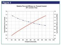
LEDs have a very quick response time (~20 nanoseconds), and instantaneously reach full light output. Therefore, many of the undesirable effects resulting from varying current levels, such as wavelength shift or forward voltage changes, can be minimized by driving the light engine at its rated current and rapidly switching that current on and off. This technique, known as PWM, is the best way to achieve stable results for applications that require dimming to less than 40% of rated current. By keeping the current at the rated level and varying the ratio of the pulse “on” time versus the time from pulse to pulse (commonly referred to as the duty cycle), the brightness can be lowered. The human eye can not detect individual light pulses at a rate greater than 200 cycles per second and averages the light intensity thereby perceiving a lower level of light.
Thermal design
With increasing power there is increased thermal load and more heat to dissipate. Higher temperatures of the LED light sources can result in reduced lumen maintenance and shorten useful life. When designing a new system, a heat sink should be selected with sufficient cooling capacity to keep the die junction below 125ºC.
If designing around an existing heat sink the maximum operating current for a given heat sink design is the lower of (1) The maximum rated current for the LED light source, or (2) The current to maintain the LED die junction temperature below the maximum specified temperature. LEDs generally must be operated at or below a junction temperature of 125°C.
The LED junction temperature (Tj) can be calculated from the array power dissipation (Pd), the array thermal resistance (Ra), the thermal resistance of the material used to attach the array to the heat sink (Rb), the ambient temperature (Ta), and the thermal resistance of the heat sink (Rh). The following formula gives the array junction temperature:
Tj = Ta + Pd (Rh + Rb + Ra)
Conclusion
LEDs offer an energy-efficient, low maintenance form of indication or illumination. The foregoing discussion demonstrates that their characteristics also make them very easy to integrate successfully into a circuit design. Providing some simple design rules are observed, these components will provide long term, reliable service.
