Matching SSL and control technology remains a challenge (MAGAZINE)
+++++
This article was published in the July/August 2013 issue of LEDs Magazine.
View the Table of Contents and download the PDF file of the complete July/August 2013 issue, or view the E-zine version in your browser.
+++++
The rapid adoption of LED light sources is rooted in energy savings, long life, and new fixture options that enable them to be used in almost any application. They are highly efficient; deliver a useful lifetime averaging 50,000 hours; and offer very good color rendering. LED lamps also emit very little infrared (IR) radiation and contain no mercury. Despite these clear advantages, issues of compatibility between LED lamps, drivers, and controls continue to cause confusion for specifiers and their customers. If they are paired improperly, performance will suffer.
The best strategy for selecting an LED product is a holistic approach that takes into consideration a variety of factors including the application type, required dimming performance, and control requirements. Mock-up installations and expensive, time-consuming testing may be necessary before customers are confident that the proposed lighting system is the best choice. Many LED component and control manufacturers are investing more time and effort into dimming testing and research, and can provide compatibility information to ensure successful LED lamp, driver, and control installation.
Looking beyond baseline efficiency
LEDs are energy efficient by design. Simply using LED lamps or fixtures can help a facility meet updated building and energy codes while reducing electricity consumption and cost. So why worry about dimming your LEDs? For the same reason you control any light source: to maximize energy savings, extend system life, enhance flexibility, increase productivity, and provide a safe, comfortable environment for building occupants. Additionally, many energy-efficiency standards are being updated to mandate more sophisticated lighting control strategies, effectively mandating dimming in many applications.
A wide range of controls are available — from a single switch or dimmer to a centralized lighting control system — to provide maximum flexibility, as well as measurement and reporting tools to help you effectively analyze the energy savings being achieved with the lighting and control installation. Sophisticated, configurable systems can allow tuning of spaces based on actual occupant usage post-installation, which over time can allow lower energy densities that surpass design goals. Furthermore, easy-to-install wireless controls facilitate simple retrofits, reducing installation and programming costs, and improving return on investment (ROI).
Regardless of the control system you choose, it is critical to work with a manufacturer who can guarantee compatibility and performance with the desired LED loads, eliminating many of the common concerns and issues that are seen with LED installations. Let’s discuss why and how to implement dimming in more detail.
Maximize savings and system life
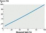
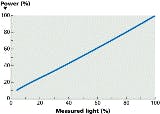
Dimming LEDs saves energy at a roughly 1:1 ratio, which matches or even exceeds the energy reduction of dimming fluorescents. This means that if you dim LEDs down to 50% of their light output you save nearly 50% of the associated energy use (Fig. 1). While it is true that LEDs are already very efficient compared to almost any other light source, you save even more energy by dimming them.
Dimming LEDs also makes them run cooler, extending the life of the electronic components in the driver, as well as the phosphor in the LEDs. This will potentially double or triple the useful life of the LED lamp or module. Research is ongoing to better quantify the relationship of dimming LEDs and lifetime extension.
Still, you must choose the fixture, driver, and control combination to meet project needs. LEDs are making great strides, and LED products now exist for replacing virtually any fixture type including general-purpose lighting, downlights, cove lights, and outdoor lighting. The type of control you choose will depend on the results you want to achieve. For example, in a lobby or atrium, a 20% minimum dimmed light level is typically acceptable. But in a conference room or restaurant, very low levels of light — dimmed down to 1% — are often desirable.
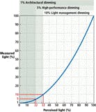
It is all too easy to neglect the importance of LED dimming range. While 10% dimming may sound appropriate for most applications, our eyes are sometimes too smart for their own good. Due to the dilation of the pupil in the human eye, lower light levels are perceived as brighter than expected. For example, a 10% light level appears to be about 33%. Even 1% dimming is perceived as a 10% light level (Fig. 2).
The expected dimming range should always be part of the product specification, but it is not always provided by the manufacturer. Furthermore, even for a given LED load, the dimming range may vary depending on the control used. Designers and specifiers need to be aware of the low-end light level that can be achieved with the proposed LED load and control combination.
If all the parts and pieces are not carefully evaluated, the result can be dimmable products that do not work as claimed. For example, you can end up with lights that never turn off completely, or that flicker, pop on, or drop out, leaving the end user with the perception that dimming LEDs does not always work.
Challenges of dimming
It is generally recognized that LEDs are inherently dimmable and controllable, so why are there so many challenges with dimming them? It is the result of the physical differences between LEDs and their predecessors including incandescent and halogen lamps.
Incandescent lamps create light by heating a tungsten wire to high temperatures in a low-pressure glass envelope, causing it to glow white hot. Electrically speaking, these are very simple devices — the more voltage delivered to the source, the hotter it got, and the more light it produced. With legacy sources the shape of the voltage waveform really didn't matter. AC, DC, phase cut, or nearly any other form would provide the same amount of light for the same RMS voltage.
LEDs behave very differently. Light is produced by subatomic processes in specially designed semiconductor materials. For a given LED device, the amount of light generated is proportional to the amount of current (not voltage) passed through the device. Furthermore, the current can flow in only one direction through an LED, meaning they can only tolerate DC current. (Note that so-called AC LEDs rely on tricks such as two diodes that are wired such that current flows through some diodes in one direction, and other diodes in the other direction.) Finally, LEDs are inherently low-voltage devices, typically requiring a large reduction in voltage from the mains wiring. These functions — reducing the voltage, regulating it to DC, and controlling the current — are all handled by a device called an LED driver.
LED drivers come in a variety of designs, constructions, and feature sets. One thing they have in common is that they do not have the same electrical properties as an incandescent load, and this difference is essentially the root cause of compatibility challenges between controls and LEDs.
Different manufacturers' drivers prioritize different requirements. Some may optimize for cost, some for size, some for lifetime, and so on. Part of the design of the driver determines how well, and how low, it will dim, and using what controls. This fact leads to two important conclusions:
The design of the driver determines the best possible dimming performance that can be achieved.
The compatibility of the driver with the control determines how well the driver will achieve this performance.
In essence, even the best control cannot make an LED lamp dim beyond its design parameters. Both poor driver design and improper pairing with a control can lead to undesired aesthetic performance, including flicker, drop-out, dead travel, or acoustic noise (buzzing).
Additionally, poor driver design and control pairing can lead to reduced lifetime of the control or load. A good driver will guarantee smooth, continuous dimming to very low light levels on a wide variety of controls with no negative impact on lifetime, matching the dimming performance that people expect from incandescent lamps. Few driver manufacturers in the industry today can reliably make this claim.
Ensuring expected performance
In order to properly align customer expectations with LED system performance, several factors need to be considered during the course of designing an LED project:
- the load type (retrofit lamp or fixture)
- the required control type
- the number of loads allowed on a control
- the dimming performance of the load and control combination
For assistance, look for trusted manufacturer resources that can assist you with the selection process, such as the LED Control Center of Excellence offered by Lutron Electronics. Let’s discuss the factors in more detail.
LED light sources come in two basic types: retrofit lamps (sometimes called screw-in lamps or LED lamps), and LED fixtures (Figs. 3 and 4). Different applications call for different solutions, but from the perspective of dimming compatibility, there is one major distinction. LED retrofit lamps have a fixed driver built into the lamp that can only be controlled via phase-cut dimming, while LED fixtures can offer a selection of drivers, available at specification time, which may provide a range of dimming performance and compatible controls.
If retrofit lamps are being used, even a proven lamp and control combination will max out performance at the lamp's published capability. Improved performance may require selection of a different lamp, perhaps from a different manufacturer. With fixtures, most manufacturers offer a range of drivers, which allows selection of the dimming performance in advance, without affecting the aesthetic or optic performance of the fixture.
For general-purpose illumination, there are four predominant control methods available:
- forward-phase control
- reverse-phase control
- 0–10V analog control
- digital control (DALI or EcoSystem)
Each of these methods has strengths and weaknesses, making some more suitable for certain applications than others. However, lighting designers and specifiers often select a fixture or control system without a full understanding of the ramifications of that selection when it comes to LED and control compatibility. Note that while other control schemes exist, including DMX or direct wireless control to lamps or fixtures, these methods are not widely used in today's general-purpose lighting applications.
Forward phase
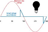
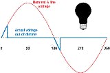
By far the most commonly used dimmer today, forward-phase controls are dominant around the world and 150 million are estimated to exist in North America alone. Thus, many LED loads claim compatibility with forward-phase dimmers. Forward-phase dimmers cut, or turn off, the front part of the 60 Hz, 120V (in North America) mains voltage sine wave (Fig. 5). The cut supply effectively reduces the RMS voltage delivered to the fixture. The more of the sine wave that is cut off, the lower the voltage, and the less energy the load uses. This method is extremely common because it is easy, generally inexpensive, and uses the xisting wiring to the fixture.
The recently released NEMA SSL7-A standard helps define the proper behavior of forward-phase dimmers and LED loads to ensure reliable operation; it also provides a basic expectation of performance. LED loads and controls marked as SSL7 compliant should remove much of the guesswork associated with compatibility for this control type.
Reverse phase
Reverse-phase dimmers operate much the same way as forward-phase dimmers do. They reduce the RMS voltage going to the load by cutting off part of the sine wave. However, unlike forward-phase dimmers that remove the front part of the sine wave, reverse-phase dimmers remove the back portion of the sine wave (Fig. 6). Like forward-phase dimmers, this reduces the RMS voltage to the fixture and uses the existing wiring.
This method was originally developed for control of electronic low voltage (ELV) transformers with low-voltage halogen lamps. These loads make up a much smaller portion of the market than their line-voltage counterparts. Therefore, reverse-phase dimmers are much less common than forward-phase dimmers. Only a small percentage of installed dimmers are compatible with ELV loads. However, due to the electrical similarities between ELV transformers and LED drivers, several driver manufacturers design their drivers to work exclusively with reverse-phase dimmers.
Analog 0–10V control
In contrast to the previous methods that rely strictly on existing wiring, the analog 0–10V scheme requires an additional pair of low-voltage wires to be run from the control to each fixture. This low-voltage pair provides the signal to the driver, which determines the target light level. A voltage of 1V tells the driver to go to the low end of its dimming range, while a voltage of 10V tells the driver to go to the high end. Generally, a line voltage switch is also included in the system to cut mains power to the driver when the lights should be off. This behavior is specified in an IEC standard, 60929, which covers only very basic functionality. For example, there is no assurance provided by the standard that smooth, continuous dimming to low light levels will occur. Mixing 0–10V fixtures from different manufacturers or using long wire runs for the 0–10V signal can cause noticeable differences in light levels across multiple fixtures.
While 0–10V allows the control wires to be run separately from the power wires, it has an inherent disadvantage when multiple control strategies are desired. By definition, all fixtures tied to the same pair of 0–10V wires are controlled together and will dim together. This fact means that for spaces with multiple control types, where fixtures must dim to different levels due to differing control inputs (such as daylight sensors, personal zone controls, and occupancy sensors), the room must be broken into multiple areas of control, each with their own 0–10V wires. Control of 0–10V loads can become very complex to design and install for all but the simplest applications. One other disadvantage of 0–10V is that any change of functionality or fixture zoning requires rewiring of the 0–10V control links.
Digital control
Like 0–10V, digital control methods, such as Lutron's EcoSystem and the Digital Addressable Lighting Interface (DALI), require an additional pair of low-voltage wires to be run to each fixture. Unlike 0–10V, however, the pair of wires sends bi-directional communication signals to each fixture, allowing individual addressability and control. DALI, a commonly used digital protocol, is also defined by the IEC, but differing interpretations of the standard can lead to incompatibilities between devices from different manufacturers even if they all claim DALI compliance. EcoSystem was developed by Lutron based on DALI and compatible fixtures are offered by Lutron and other lighting companies such as Cree and GE Lighting. Compatible fixtures provide guaranteed control compatibility, no matter which manufacturer is selected.
Digital control methods allow easy layering of control schemes. Each fixture can behave independently from all others if that is desired to achieve lighting goals. Digital technologies enable advanced functionality and zoning of fixtures through a simple software interface, with no modification of the wiring required. Digital controls allow flexibility in space configuration and reuse. Digital fixture control most effectively unlocks the capability of smart lighting promised by LEDs.
Control ratings
As was described previously, LED loads do not electrically behave like incandescent loads, leading to differing performance on different controls. However, beyond aesthetic performance, the electrical characteristics of many LED loads cause additional stresses on controls, beyond what their wattage alone may indicate. This complicates determining how many loads — for instance, how many retrofit lamps or downlights — can be reliably connected to a control.
The high inrush currents, repetitive peak currents, and RMS currents that can occur when phase-cut dimmers are used with LEDs means that most controls rated for incandescent loads cannot handle nearly the same wattage of LED loads. Generally, only detailed electrical testing can determine the proper minimum and maximum number of loads that can be connected to a control.
What many users do not understand is the effect of the lamp selection on the regulatory rating of the control. Controls are tested and listed with a specific load type in mind. For example, UL may rate a control as appropriate for incandescent or magnetic low voltage (MLV) loads. Using them on other load types, such as ELV loads even at the same voltage level, means they are being used beyond their original design and testing, which can lead to unexpected behavior or decreased reliability.
Most existing incandescent dimmers have not been designed, rated, or tested by UL or another nationally recognized testing laboratory (NRTL) with LED loads. Fortunately, many control manufacturers have recently released dimmers explicitly rated for controlling LEDs, such as the C•L dimmer family from Lutron Electronics. These types of controls have LED-specific ratings, allowing the actual wattage of the LED to be used to determine the maximum loading. In summary, the manufacturer of the control should always be consulted to determine whether or not the control in question has been tested on LEDs, and that the control is not overloaded.
A holistic approach to LED control can help meet and exceed customer expectations. Technologies are improving; control options, available literature, and general knowledge are expanding; and LEDs can now be effectively used in virtually any type of commercial application. By choosing the right manufacturer, control, and driver, and considering key issues, it will be easier than ever to provide customers with LED lighting and a control system that meets energy-saving, performance, and aesthetic expectations.
