Understand both static and transient thermal management in LED-based developments (MAGAZINE)
GILES HUMPSTON explains the intricacies of cooling LEDs and modeling the thermal path to ensure reliable solid-state lighting product developments.
LEDs are complex devices. Not only are there the usual issues associated with the design and operation of semiconductors, but LEDs are primarily built to emit light. Thus there will be further system complexities of optical coatings, beam management devices like reflectors and lenses, and for most white-light emitters, wavelength-conversion phosphors. Still, thermal management remains paramount for reliable solid-state lighting (SSL) products that deliver to their full performance potential in flux produced. Moreover, you need to understand how to cool LEDs in both static and transient implementations.
Interested in more articles & announcements on thermal management?
For LEDs, two thermal management parameters need to be respected. They are the desired operating temperature and maximum operating temperature. As a general guideline, the desired operating temperature needs to be as low as possible. Achieving this will ensure high electro-optic efficiency with good spectrum quality and long device life. Operation at elevated temperature not only degrades the light produced by LEDs, in terms of quality and quantity, but also eventually triggers a number of failure mechanisms.
LED manufacturers are well versed in these pitfalls and are able to design products that function perfectly happily up to a junction temperature of about 130°C. Printed-circuit board (PCB) temperatures are around 10°C cooler due to the thermal resistance of the LED package. Above the rated junction temperature, LED life roughly halves for every 10°C rise.
LEDs are relatively inefficient at converting electrons to phonons. A high-brightness white LED can approach 40% efficiency, while a UV-C LED may only be 5% efficient. In both cases, the surplus heat must be removed by conduction to prevent overheating. Responsibility for this falls to the LED light source or luminaire designer.
Static cooling of LEDs
The conventional approach to keeping LEDs cool is to mount the semiconductor devices on a heat sink. The heat from the LEDs passes into the heat sink by conduction and is then dissipated into the air. In cases where the heat is removed by water, or another fluid, the heat sink is sometimes referred to as a cold plate, since the associated heat removal system is frequently engineered for the working fluid to be at a fixed temperature that is below room ambient.
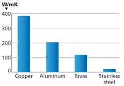
FIG. 1. Materials have varying degrees of thermal conductivity.
Accomplishing effective transport of heat from the LED to the heat sink should just be a matter of specifying a material of high thermal conductivity. For example, from the chart in Fig. 1, it would appear that copper is superior to aluminum and brass, which are both better than stainless steel.
While it is true that copper is the best thermal conductor of these metals, the metric of thermal conductivity does not account for the thickness of the material. What matters in terms of the ability to transfer heat by conduction through a material is the thermal resistance, which is the thickness divided by the thermal conductivity.
Dielectrics and airflow
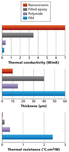
Consider, for example, the thermal PCBs on which mid- and high-power LED arrays are often built. On the top surface there is copper tracking to make electrical connection to the LEDs, while underneath there is a plate of aluminum to conduct the heat away. Between the copper and the aluminum there is a dielectric layer to prevent electrical shorting of the copper tracks to the aluminum. Various manufacturers have taken different approaches in the selection of dielectric material, which span the complete spectrum from organic to inorganic compounds. As Fig. 2 shows, the dielectric material with the smallest thermal resistance, by nearly an order of magnitude, is the one that can be applied thinnest while still providing the required dielectric isolation.
FIG. 2. The thickness of a dielectric material impacts thermal resistance.
Unfortunately, even Fig. 2 does not present a complete picture. In the thermal path between the LED and the heat sink fins, assuming the device is air-cooled, there will be a number of interfaces. Some will be bridged by solder, some by adhesives, and others will be pressed together - for example, using screws. These joints present additional barriers to the conduction of heat, the magnitude of which can be large, difficult to predict, and subject to change over time. The thermal resistance each presents is termed the interface resistance.
Related article: Determine LED temperature effects for reliable SSL products
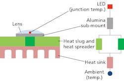
The series/parallel addition of all the thermal resistances and interface resistances in the system is called the thermal impedance and permits the conduction path to be designed to keep LEDs cool. Calculation is analogous to electrical resistor networks. In Fig. 3, voltage is essentially temperature in calculations, current is heat flux, and the resulting electrical resistance is thermal resistance.
FIG. 3. In development work, you can rely on an electrical resistance equivalent of the thermal conduction path. To arrive at a complete system model of thermal impedance, thermal interface resistances must be added at each transition between materials.
Transient cooling of LEDs
The prior discussion presumes a steady-state scenario where the LED is permanently energized and the heat sink is continuously dissipating the thermal energy to ambient air. There are two situations where this thermal model breaks down. These are at switch-on of the LED and more generally in pulsed operation. Surprisingly, it is possible to design a thermal path that will keep an LED cool when operating continuously but will permit it to overheat at switch-on. When operated like this, the associated thermal excursion can lead to abrupt failure of the LED in a manner analogous to the switch-on breakage of a tungsten lamp filament. The design of a thermal solution for LEDs therefore needs to take into account transient operation and include both time and spatial variables.
Time dependence
The time component of transient cooling arises due to the specific heat capacity of the materials in the thermal path. This can be added to the electrical model of thermal resistance as capacitors (Fig. 4). The heat capacity of a material is the energy required to raise a fixed mass by a given temperature. With a step function of heat applied, it results in a thermal time constant describing the temperature rise versus time. Thus the thermal response of the system is the superposition of many exponential curves each with different time constants and corresponding to different components in the heat path.
FIG. 4. Time dependence of thermal conduction arises due to the heat capacity of the materials in the system, for which the electrical equivalence model is a low-pass RC filter.
The electrical model analogy means that the term thermal impedance is sometimes used to describe the time-related thermal properties of materials. Note that there is potential for confusion with the term thermal impedance that describes the static thermal resistance of a complete system.
Cumulative structure function
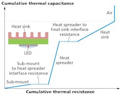
A useful visual tool to analyze the role of materials in determining the time component of the heat conduction path is the cumulative structure function (Fig. 5). It is the thermal impedance of a system expressed as a graph of thermal capacity versus thermal resistance for the entire heat flow path. The origin corresponds to the location where the power is generated and the end point is usually associated with ambient air.
FIG. 5. The cumulative structure function provides a map of the thermal capacity and thermal resistance of the path between the LED die and its heat sink.
Because all materials possess an element of both thermal capacitance and thermal resistance, each component in the system is depicted as a line with a specific gradient. Interfaces between solid materials have resistance but essentially zero thermal capacity and so are present as horizontal lines, while the end point of ambient air has effectively infinite capacity for no change in resistance and so is a vertical line.
Related article: UV and industrial LED applications require efficient thermal substrates
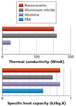
With the start and end point of the cumulative structure function fixed, it is possible to conceive multiple cooling solutions with identical overall thermal resistance but substantially different transient behavior. For example, the chart in Fig. 6 shows the thermal conductivity and heat capacity of four materials that might be part of an LED thermal management solution. The ranking order changes with the parameter considered more important.
FIG. 6. The charts depict the thermal conductivity and heat capacity of various materials.
In pulsed operation of LEDs - for example, a machine-vision system designed to freeze images on a fast conveyor where the flash duration is measured in microseconds - it is preferable to have high heat capacity adjacent to the semiconductor. For the usual role of continuous operation, low thermal resistance between the die and heat sink is more important.
In theory, the time dependence of transient cooling should mean the temperature of the LED starts at ambient and rises asymptotically to saturate at a steady-state value. However, the situation in reality is more complex owing to the other dynamic term, namely spatial dependence.
Spatial dependence
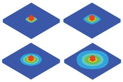
The spatial component of transient cooling arises from the propensity of heat to spread in all directions. Consider, for example, an LED mounted on a large, thin metal plate. Initially, the entire plate is at ambient temperature. The LED acts as a point heat source. At switch-on, the LED will generate heat that transfers into the plate by conduction. The heat will pass rapidly through the plate and raise the temperature of the region underneath the LED. Thus, initially, only a small volume of the plate is being used to cool the LED. The conductivity of the metal plate means that some of the heat from the LED will spread laterally within the thickness of the plate, eventually appearing at the surface some distance removed from the LED (illustrated in Fig. 7). Thus the volume of the metal plate actively engaged in cooling the LED will increase with time, causing the apparent thermal resistance and heat capacity to also change.
FIG. 7. A simple finite-element thermal model of a hot body on a thin metal plate demonstrates spatial dependence as a change in the volume of the plate material participating in cooling. The models were calculated for increasing time from top left to bottom right.
To a very limited extent, the spatial component of transient cooling can be incorporated into the electrical model of heat transfer by including additional RC networks to provide second-order and higher time dependency. However, due to other effects, such as the nonlinearity of materials properties with temperature, the electrical model approach can be favorably replaced by finite element and other methods of calculation.
Spatial dependence is particularly relevant where there is an interface or layer of high thermal resistance in the path. By taking steps to spread the heat over the largest possible area ahead of this barrier, far better cooling of LEDs is possible in both steady-state and pulsed operation.
Convection and radiation
Any material that is above ambient temperature will lose heat by convection and radiation. While these are the dominant mechanisms of cooling for tungsten filament lamps, they play only a small role in the thermal management of LEDs. Nevertheless, they should still be included in any model to ensure the closest possible match to the real-world situation.
In conclusion, LEDs must be cooled to achieve best efficiency and ensure the stability of their optical output and longevity. A simple steady-state model of thermal conduction can be constructed using a model based on electrical components. However, to properly understand the thermal path and in particular its behavior under transient conditions, it is better to use a tool that can accommodate time-, spatial-, and temperature-dependent effects.
The time and spatial dependence of thermal conduction explains why there is a hierarchy in terms of materials selection in which the preference for high specific heat capacity or good thermal conductivity changes with the location of the material in the thermal path and the expected mode of operation of the LED.
GILES HUMPSTON is the field applications manager at Cambridge Nanotherm ([email protected]; camnano.com).

