Reflective liquid crystal displays (RLCDs) offer the benefits of traditional backlit LCDs — high resolution, good color, high refresh rate and robust manufacturing — while having the additional benefits of very low power and sunlight readability. This is achieved by effectively replacing the LCD backlight with a mirror. The problem is that by removing the light source, RLCDs cannot be viewed in low-lighting conditions, therefore requiring a front light panel (FLP). Proper lighting of RLCDs is non-trivial as they offer a unique set of challenges that traditional display lighting technologies are fundamentally ill-equipped to overcome.
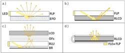
Figure 1 shows sideview schematics of various display systems in order to illustrate some of the requirements for RLCD lighting. A typical E-ink electrophoretic display (EPD) with front light is shown in 1a. Since the display is paper-like, light rays leaked at slight angles from the FLP shown in yellow will hit the display and scatter in all directions. In comparison, 1b shows the mirror-like RLCD reflecting the light with only slight scatter. Backlit LCDs (1c) overcome the low-scatter of the LCD by adding multiple optical films including diffusers and a back reflector. These additional films cannot be used in a front lighting system because they substantially reduce the image quality when viewing through them.
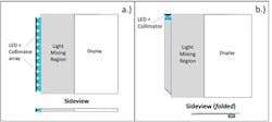
Traditional edge-lighting is shown in Figure 2a with LEDs lined along a sheet of similar thickness. Both frontlit EPDs and back-lit LCDs use this approach and reduce LED “hot-spotting” at the display edge by simply applying a 2D compensation to the light extraction pattern. However, this method cannot be used in the RLCD systems because the hot spots move with viewer’s position. Therefore, a RLCD FLP must deliver uniform lighting intensity by position and angle over the entire display area.
Figure 1: Sideview schematic of (a) Electrophoretic display with edge-lit front light, (b) RLCD with edge-lit front light.(c) LCD with edge-lit backlight unit / optical films / back reflector and (d) The FLEx front light on RLCD.
How FLEx Compares:
FLEx has developed and commercialized a new high performance optical system for lighting 25 to 75 micron thick lightguide films. As shown in Figure 2b, the system includes a proprietary Lightbar for efficiently and uniformly coupling light into film that is much thinner than the size of the LED. There is also a flexible Light Mixing Region and Display Region, where the light is extracted from the film to light the display. The light is delivered to the RLCD at a range of angles as shown in Figure 1d. The many benefits of the FLEx system combine to overcome the previous limitations in RLCD front lighting. The net result is a breakthrough in low power displays with high uniformity, good contrast, good color gamut and full viewing angles.
Figure 2: Schematics of (a) Traditional edge-lighting and (b) the FLEx optical system.
The FLEx optical system integrated with a 4.4” RLCD is shown in Figure 3. As shown in the front view 3a, the flexibility of the film enables a completely bezel-free system. The Lightbar includes an FPC to connect to the device PCB in order to power the LED(s).
Figure 3b shows the compact Lightbar folded behind the display system with a long Mixing Region to ensure high uniformity of the display illumination. For higher efficiency and optical gain, the Lightbar includes collimation optics between the LED(s) and Lightbar. The Lightbar and film are completely protected so additional touch panels and/or cover lenses can be directly bonded with liquid optically clear adhesive or pressure sensitive adhesive. The FLP may be above or below touch or diffuser layers.
Figure 3: The FLEx FLP integrated on a 4.4” RLCD (a) Front view and (b) Back view
The FLEx Benefits:
Thin and Flexible
The 50 micron lightguide film from FLEx is an essential component of the high clarity and uniform front light system. Since the film is on the viewer side of the display, any micropatterning must be invisible and not reduce the display clarity. It has been shown that the visibility of the micropattern scales with the lightguide thickness. Therefore, a 10X thinner lightguide results in 10X lower visibility of the features. The thin lightguide also reduces the overall system size/weight while importantly minimizing the thickness of material above the display. Finally, the flexible film enables the Lightbar to be folded behind the display for maximum uniformity with a bezel-free display.
Uniform Input
The FLEx Lightbar provides better light uniformity than an array of discrete LEDs along an edge. A Light Mixing Region between the Lightbar and display section further improves this uniformity. The result is an even field of light entering the Display without the optical artifacts of “hot-spotting” or “laser-beaming.” As shown in Figure 4b, the long mixing region of the FLEx System can be folded behind the display, unlike traditional edge-light sheets (4a). The substantial uniformity can also be utilized for color-mixing and collimated lighting systems.
Figure 4: Schematics of collimated lightguide systems with (a) traditional edge-lit system and (b) the FLEx System. Unlike the edge-lit system, the FLEx System can be folded behind the display as shown in the Sideview.
Collimated light
In typical edge-lit lightguides the illumination rays are distributed over a wide range of angles to allow for even mixing of the light. To narrow this illumination, there must be an array of collimators between the LEDs and lightguide as shown in Figure 4a. This adds manufacturing issues but most importantly requires a long region to mix the
illumination before the display portion. Since the lightguide is not ultra-flexible, this then requires a bezel region around the display. As shown in Figure 4b, FLEx can use a single collimator for system simplicity and the Light Mixing Region and Lightbar can be folded behind the display.
Collimated light within the Lightguide enables two main advantages. First, the narrower the angles of propagating light, the more efficiently the light can be directed towards the display in useful lighting angles. This results in a high contrast front light with light delivered near the display normal for high gain. Figure 5 shows example lighting angles that FLEx delivers to various display types. The second advantage is high efficiency coupling into the lightguide. Unlike a backlight, which is surrounded by air, the front light must have a protective cladding to allow it to bond to the front of the display and other layers. This cladding lowers the acceptance angle or numerical aperture of the lightguide. The collimator compensates for this and also removes the need for any airgap between the LED and lightguide, further increasing the efficiency.
Figure 5: Examples of FLEx lighting angles and color coordinates for (a) broad peak near normal (b) narrow peak near normal and (c) broad peak off-normal.
Full panel integration
The combination of benefits enables full device integration with the RLCD, touch panel and cover-lens in a completely bezel-free design. The FLP film can be placed above or below most touch-panels in the display stack. The Lightbar portion has been designed to be a similar thickness to a device PCB or battery. This allows the designer to place the Lightbar adjacent to these components as to not add thickness to the device. Besides folding the Lightbar around the display, the film can be rolled around the Lightbar for different packaging options. Although FLEx typically includes the LED/FPC, it can also be integrated into the LCD FPC or device PCB. Overall, there are many options to enable this new functionality in compact form factors.


