Virtual prototyping LED products across the supply chain speeds development — Part 2 (MAGAZINE)
In Part 1 of this article, we explored a development process that has been created by the Delphi4LED consortium that would allow effective simulation of a design to speed time to market. In traditional developments, much time is spent on prototyping and laboratory testing LED-based designs. The consortium has developed a multi-domain (thermal-optical-electrical) approach to design and simulation tools that can be applied to solid-state lighting (SSL) product development. In the first part of the article, we described the basics of the modeling scheme. In this second part, we will describe how our team pursued pilot implementations of a modeled luminaire in two different scenarios in terms of organization size and resources.
Both within the Delphi4LED consortium and in real life, we identified two companies that have significantly different daily design practices, based on company culture and available technical/financial resources. Based on these profiles, a pilot study and then demonstration experiments were set up by the Delphi4LED consortium.3*
For the pilot, we conducted an implementation of the proposed Delphi4LED workflow by the smaller-to-medium–sized design company. A set of models was created and combined into an Excel spreadsheet application that would be used as the simplified design/virtual prototyping tool. Based on prior characterization of LEDs foreseen for the project demonstrators, our team at BME (Budapest University of Technology and Economics, and one of the academic consortium members) created a SPICE-like, chip-level, multi-domain model and extracted the model parameters. A DCTM (dynamic compact thermal model) of the package was also created.
Characterization and simulation application
Pre-characterization of different module substrates and different heat-sink designs (Fig. 1) was also performed. This way, the compact thermal models — thermal N-port models for the substrates and equivalent substrate-to-ambient thermal resistances for heat sinks — were also created and included in the spreadsheet application.
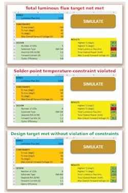
Fig. 2 depicts the simulation application. The user interface allows a product developer to set major design goals — for example, total luminous flux in this demo. The developer would enter the target output in the blue field in Fig. 2. Next, the developer would enter design constraints in the orange fields. In this example, the constraints include projected ambient temperature, maximum allowed junction and solder point temperatures, and maximum allowed total forward voltage. The developer could select the number of LEDs, substrate, and heat-sink types from pull-down menus and set the optical efficiency and the total forward current of the LED driver as input in the light-green fields.
Three design alternatives are shown in Fig. 2. After multi-domain simulation (where thermal and electro-optical co-simulation of the luminaire is performed in an iterative manner), the success/failure of meeting the set design constraints was indicated with a semaphore-like results feedback. For example, in the first of the three iterations, the five LEDs selected didn’t meet total flux requirements as indicated in the red-highlighted field on the right side under results.
In the second iteration, the number of LEDs was increased to six. That change enabled the configuration to meet flux requirements but resulted in a failure in terms of solder-point temperature. In the third iteration, the type of substrate was changed and yielded a configuration that would meet design goals and not exceed any critical constraints.
The quickly iterative simulation enables the developer to select the right combination of the number of LEDs, substrate, and heat-sink designs. The necessary optical efficiency and total forward current could be found by similar virtual experiments instead of measuring different physical product prototypes.
Tale of two companies
For the second part of the pilot implementation, four demonstration experiments were conducted: two for the large company and two for the small-to-medium–sized company. In each case, the experiments were intended to compare their old way of development to our new method. Also as part of the demo, an independent industrial photometric test laboratory performed the necessary pre-production testing.
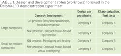
All the design and development phases of a luminaire (Fig. 1 in Part 1 of this article) were carried out with the ambition to meet the major specs. The design process was monitored for each development style shown in Table 1, with the aim of measuring costs of development (time spent, incurred personal costs) to the realization of samples as well as costs related to lab measurements and characterization.3,20
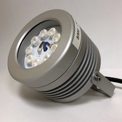
The smaller company’s design processes were tracked using a spreadsheet. We recorded and compared the time spent on each design development step performed in the company’s traditional trial-and-error–based approach, then performing the same design tasks using virtual prototyping were recorded and compared. The final luminaire sample developed with this virtual prototyping approach is shown in Fig. 3.
For the large company, LED package compact models were created and used via their additions to a commercial CFD (computational fluid dynamics) tool that also offers design optimization options. The input was an MCAD model of the luminaire and the test-based LED models. The final, optimized product virtual prototype and the corresponding physical sample were created.
Four luminaires were developed in this demo: two samples with and two samples without using compact-model–based virtual prototyping, following design style corresponding to the two company profiles (small-to-medium or large company). Cost and time criteria of the Delphi4LED approach in LED-based product development and the old design practices (Table 2) were also compared.
Proof of concept and summary
With this first demonstration experiment of the Delphi4LED project, we aimed to provide a proof of concept of the project. As a result of our tests based on real company design practices, we estimate that design cost savings of 30–40% can be achieved through avoiding building and testing physical product prototypes and through increased efficiency of designers by using multi-domain simulations using compact models of LEDs and luminaires. The simulation-based optimizations also lead to a faster “time to pre-industrial sample,” with a time reduction of about 30%.
In this Delphi4LED project, we developed new methodologies for compact modeling of LED products. The multi-domain nature of LED operation is treated at the chip level, resulting in a multi-domain LED model that can be implemented both in generic SPICE circuit simulators and also as Visual Basic macros in a spreadsheet application. With an approach similar to the standard DELPHI methodology15, boundary-condition–independent compact models of LED packages are created.17 These, combined with the aforementioned chip-level multi-domain model14 and the compact thermal models of module substrates and luminaires allow a system-level, multi-domain simulation of an LED application. The combined chip+package+substrate+luminaire model is the “digital twin” of a foreseen luminaire. This virtual prototype allows computer simulation assisted or computer-simulation–based optimization of an LED application.
*Editor’s note: For continuity, all references from Part 1 of this series have been cited at the end of the text.
REFERENCES
1. R. Bornoff et al., "Delphi4LED - From Measurements to Standardized Multi-Domain Compact Models of LEDs: a New European R&D Project for Predictive and Efficient Multi-domain Modeling and Simulation of LEDs at all Integration Levels Along the SSL Supply Chain," Proc. THERMINIC, 174-189 (Sept. 2016), DOI: 10.1109/THERMINIC.2016.7749048.
2. G. Martin et al., "Delphi4LED - from measurements to standardized multi-domain compact models of light emitting diodes (LED)," Electron. Cooling Mag., 20-23 (Aug. 2017).3. C. Marty et al., "Design flow for the development of optimized LED luminaires using multi-domain compact model simulations," Proc. THERMINIC (Sept. 2018), DOI: 10.1109/THERMINIC.2018.8593318.
4. JEDEC JESD51-14 Standard, "Transient Dual Interface Test Method for the Measurement of the Thermal Resistance Junction-To-Case of Semiconductor Devices with Heat Flow through a Single Path" (2010).
5. JEDEC JESD51-51 Standard, "Implementation of the Electrical Test Method for the Measurement of Real Thermal Resistance and Impedance of Light-Emitting Diodes with Exposed Cooling" (2012).
6. JEDEC JESD51-52 Standard, "Guidelines for Combining CIE 127:2007 Total Flux Measurements with Thermal Measurements of LEDs with Exposed Cooling Surface" (2012).
7. CIE 225:2017 Technical Report, "Optical Measurement of High-Power LEDs," ISBN 978-3-902842-12-1, DOI: 10.25039/TR.225.2017 (2017).
8. G. Farkas, A. Poppe, "Thermal testing of LEDs," Thermal Management for LED Applications, 73-165, Springer (2014), DOI: 10.1007/978-1-4614-5091-7_4.
9. Scope of the CIE TC2-84 technical committee.
10. A. Poppe, "Multi-domain compact modeling of LEDs: an overview of models and experimental data," Microelectron. J, 46, 12 A, 1138-1151 (2015), DOI: 10.1016/j. mejo.2015.09.013.
11. A. Poppe, J. Hegedüs, and A. Szalai, "Multi-domain modeling of power LEDs based on measured isothermal I-V-L characteristics," Proc. CIE Lighting Quality & Energy Efficiency Conf., 318-327 (Mar. 2016).
12. G. Hantos et al., "Measurement issues in LED characterization for Delphi4LED style combined electrical-optical-thermal LED modeling," Proc. EPTC (Dec. 2017), DOI: 10.1109/EPTC.2017.8277493.
13. G. Farkas et al., "LED characterization within the Delphi-4LED Project," Proc. ITHERM (May/June 2018), DOI: 10.1109/ITHERM.2018.8419602.
14. A. Poppe et al., "Multi-domain modelling of LEDs for supporting virtual prototyping of luminaires," Energies, special issue on Thermal and Electrothermal System Simulation, submitted (2019).
15. JEDEC JESD15-4 Standard, “DELPHI Compact Thermal Model Guideline” (2008).
16. R. Bornoff, G. Farkas, L. Gaál, M. Rencz, and A. Poppe, “LED 3D Thermal Model Calibration against Measurement,” Proc. EuroSimE (April 2018), DOI: 10.1109/EuroSimE.2018.8369929.
17. R. Bornoff, “Extraction of Boundary Condition Independent Dynamic Compact Thermal Models of LEDs – a Delphi4LED Methodology,” Energies, special issue on Thermal and Electrothermal System Simulation, submitted (2019).
18. A. Poppe, J. Hegedüs, A. Szalai, R. Bornoff, and J. Dyson, “Creating multi-port thermal network models of LED luminaires for application in system level multi-domain simulation using Spice-like solvers,” Proc. SEMI-THERM, 44–49 (March 2016), DOI: 10.1109/SEMITHERM.2016.7458444.
19. S. Lungten et al., “Dynamic Compact Thermal Model Extraction for LED Packages Using Model Order Reduction Techniques,” Proc.THERMINIC (Sept. 2017), DOI: 10.1109/THERMINIC.2017.8233791.
20. G. Martin et al., “Luminaire Digital Design Flow with Multi-Domain Digital Twins of LEDs,” Energies, special issue on Thermal and Electro-thermal System Simulation, submitted (2019).
Get to know our experts
ANDRÁS POPPE and ROBIN BORNOFF represent Mentor, A Siemens Business; and GUSZTAV HANTOS and JANOS HEGEDUS represent BME - Budapest University of Technology and Economics.


![The DesignLights Consortium continues to make progress in shifting outdoor lighting products and implementation practices toward a more restrained and thoughtful strategy. [Image does not represent a DLC qualified fixture.] The DesignLights Consortium continues to make progress in shifting outdoor lighting products and implementation practices toward a more restrained and thoughtful strategy. [Image does not represent a DLC qualified fixture.]](https://img.ledsmagazine.com/files/base/ebm/leds/image/2024/08/66be810888ae93f656446f61-dreamstime_m_265700653.png?auto=format,compress&fit=&q=45&h=139&height=139&w=250&width=250)