Third-generation instruments simplify short-pulse testing (MAGAZINE)
My April/May 2022 LEDs Magazine article discussed the decline of the 20-ms LED measurement pulse and the emergence of improved short-pulse measurement methods documented in new standards from the Illuminating Engineering Society (IES) and Commission Internationale de l’Eclairage (International Commission on Illumination, CIE). The described methods, which use pulses as short as 10 µs, overcome significant heating-induced errors with optimized LEDs as well as LEDs operated at high current densities. Working with pulses more than three orders of magnitude shorter challenges test instruments. This article summarizes the drawbacks and presents improved tools that simplify testing: third-generation source/measure instruments, programmable spectrometers, and software that allow labs and production facilities to realize the promise of these methods.
Powering the LED
LED testing labs typically use a source/measure unit (SMU) to power LEDs. First introduced by Keithley instruments in 1989, first-generation SMUs operated at low power. They treated the device under test as a static element, and current rise/fall times were in the hundreds of microseconds. Timing for many actions, such as forward voltage (VF) measurement, was undefined, as technicians assumed that the voltage would not change during the measurement.
Second-generation SMUs sped up timing significantly, offering current rise/fall times in the tens of microseconds. Still, pulse and measurement timing remained uncertain, so measurements often exhibited unacceptable variability. Test developers performed repeated measurements with averaging, which lengthened test times and introduced more junction heating.
Second-generation SMUs are not usable for short-pulse testing because the latest standardized test methods require current pulses as short as 10 µs. Also, instead of a point measurement at an indeterminate time, the LED’s VF must be averaged over an aperture that matches the optical integration time — and be precisely aligned with the optical measurement.
Early adopters of short-pulse test methods rigged together instruments or built custom electronics to perform synchronized source/measure functions. For example, the requirement to align VF capture with the optical measurement necessitates a programmable digitizer that can trigger — with nanosecond accuracy — sample voltages with high fidelity and calculate averages. Custom software was often required to make the various custom and commercial instruments work together and to support short-pulse triggering and data processing. Altogether, the investment was beyond the resources of most labs, so many continued to use long-pulse methods even after identifying the need for reduced heating.
Labs that did brave the financial challenge found themselves facing additional engineering hurdles:
- Cable inductance, a nonissue with 20-ms pulses, slows and distorts current rise/fall times, and it increases the compliance voltage needed to drive the current — sometimes as much as 30V above the LED’s forward voltage.
- Pulse width and period timing errors as short as 2 µs to 3 µs can introduce measurement errors, which are insignificant when testing with long pulses but unacceptable as pulse widths approach 10 µs.
- Slow pulse rise/fall times, combined with the LED’s increased efficiency at low currents, introduce the rise-and-fall error, a previously unknown optical measurement error.
- High-current-density measurements require high test currents, often more than 10A, which is the typical maximum of many pulsed current-source instruments.
Collectively, these challenges and their workarounds slowed the adoption of short-pulse methods; many labs used short-pulse methods only for critical tasks such as quantum efficiency research.
Third-generation SMUs on the market are designed with short-pulse testing in mind. With better timing systems than their predecessors, these SMUs include some facility for overcoming circuit inductance to produce faster rise/fall times. To support the timed- and aligned-voltage sensing requirements, all third-generation SMUs also include voltage digitizing functions.
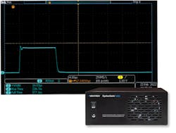
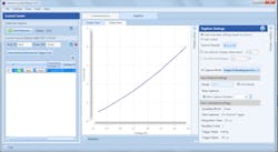
For example, the hardware-based timing system of the SMU shown in Fig. 1 pulses at full power from 1 µs to DC. It has programmable load/cable compensation, and its 18-bit digitizer and hardware triggering/timing system automatically aligns optical and voltage measurements.1 Unlike prior general-purpose SMUs, this device is optimized for optoelectronic testing with built-in support for sweep measurements, pulsed waveform captures, and logarithmically spaced measurements that support thermal impedance plots and structure functions. For many tasks, no programming is necessary and some tasks, such as the I-V plot shown in Fig. 2, take only milliseconds to complete.
Current superposition, a novel technique borrowed from circuit analysis, delivers high currents up to 60A over long cables. Superposition reduces the effect of inductance, speeds rise/fall times, and allows the current to be equally split over several conductors. This feature eliminates the risk of burned pins and wafers when using multiple probe pins to carry high currents to components tested at the wafer level.
The integrating spectrometer
Once the LED is correctly powered, equipment must gather and analyze the produced light. Most setups use a spectroradiometer (also called a spectrometer), which includes precision optics and electronics. The best instruments are expensive; a typical high-end spectrometer may be five to 10 times the cost of an SMU.
The good news is that in many instances, the spectrometer can remain in place when switching from 20-ms measurements to short-pulse measurements. The integration time — the time during which the spectrometer gathers light — must be adjusted, but the instrument can still make the required light measurement. The chief characteristic that determines the possibility of reuse is the spectrometer’s dark signal, or the residual signal collected when no light is present. If the dark signal is too large, it overwhelms the gathered light, especially when testing low-output LEDs. High-performance spectrometers have a low dark-signal characteristic. When combined with a third-generation SMU and appropriate software plug-ins, they will make excellent measurements with new short-pulse methods.2
Improved data
The L-I curve, a common measurement, demonstrates the benefits of short-pulse testing. L-I curves are generated using a sweep measurement, or a series of single measurements made at increasing currents. The sweep can use pulsed- or contiguous-current steps known as a staircase sweep. In a staircase sweep, the LED is driven continuously; heat accumulates from the beginning of the sweep to the end. Thus, early measurements occur at a temperature close to the LED’s ambient condition and later measurements at a higher temperature. Pulsed sweeps can be significantly more accurate, but long-pulse sweeps still suffer from single-measurement and cumulative heating.
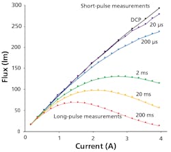
Figure 3 shows pulsed L-I sweep curves for an aluminum gallium indium phosphide LED with a die area of 1 mm2 and a nominal current of 1A. Tests used current pulses of various widths, ranging from 200-ms long pulses to 20-µs short pulses. Notice that all the curves are similar to about 50% of the nominal 1A current. However, junction heating causes the light output to droop above that current. For the longest current pulses, this droop is so significant that the curve begins to decline with increasing current, a phenomenon called rollover. The 20-µs pulses produce the flattest curve, but this curve is impacted by measurement errors. The black curve was made using the Differential Continuous Pulse (DCP) method developed by Nichia. The DCP curve exhibits the least droop and is free from measurement noise.
Short-pulse testing will drive device advances
As the industry transitions to short-pulse testing, it no longer faces the arduous task of integrating and tuning various instruments to realize adequate short-pulse test systems. Third-generation SMUs support short-pulse methods without a big investment. The resulting enhanced data enables solid-state lighting product developers to create more efficient and cost-effective ultraviolet and visible-light LED systems. More reliable test methods will also allow LED chip developers to fully understand device performance at high current densities and improve their component designs.
References
Get to know our expert
JEFF HULETT is CTO and founder of test & measurement specialist firm Vektrex, based in San Diego, CA. Over the course of his career, Hulett has acted as chief engineer on products ranging from single-board computers for spaceflight to power supplies for DNA sequencing systems to current sources used in the LED and laser industries for product and system evaluation. Hulett holds several patents related to LED testing and has authored technical articles for publications such as LEDs Magazine and Photonics Spectra. He also serves as chair of the Illuminating Engineering Society’s LM-80 Working Group.
Vektrex supplies test & measurement equipment such as source/measure units and current sources that support evaluation methods described in this article.
Online article extended with additional image and text — abridged version published in the June 2022 issue of LEDs Magazine.
For up-to-the-minute LED and SSL updates, follow us on Twitter. You’ll find curated content and commentary, as well as information on industry events, webcasts, and surveys on our LinkedIn page and our Facebook page.


![The DesignLights Consortium continues to make progress in shifting outdoor lighting products and implementation practices toward a more restrained and thoughtful strategy. [Image does not represent a DLC qualified fixture.] The DesignLights Consortium continues to make progress in shifting outdoor lighting products and implementation practices toward a more restrained and thoughtful strategy. [Image does not represent a DLC qualified fixture.]](https://img.ledsmagazine.com/files/base/ebm/leds/image/2024/08/66be810888ae93f656446f61-dreamstime_m_265700653.png?auto=format,compress&fit=&q=45&h=139&height=139&w=250&width=250)
